English
 Español
 Français
 عربى
عربى italiano
The ASCE 7-10 wind speed map is a set of three separate maps, not a single national map. Each map is linked to a different Risk Category and uses three-second gust speeds with a distinct mean recurrence interval. If you design or specify light poles, street lighting, or any outdoor structure in the United States, these maps determine the starting wind speed for your load calculation. The practical takeaway is direct: a higher Risk Category means a higher design wind speed, which means a stronger pole and a larger foundation. The sections below break down the map, explain how to apply it, and connect it to real pole selection decisions.
Content
- 1 What Is the ASCE 7-10 Wind Speed Map?
- 2 How to Read the ASCE 7-10 Wind Speed Map for a Site
- 3 Why a Small Increase in Wind Speed Creates a Large Jump in Load
- 4 What This Means for Light Poles and Street Lighting
- 5 Practical Steps for Specifying a Pole Under ASCE 7-10
- 6 The Bottom Line: Match the Pole to the Map
What Is the ASCE 7-10 Wind Speed Map?
ASCE 7-10, "Minimum Design Loads for Buildings and Other Structures," changed the way wind speeds are mapped in the United States. Instead of using the older fastest-mile wind speed, the standard adopted the three-second gust wind speed as the basic design variable. The map is presented in three editions: Risk Category I, Risk Category II, and Risk Categories III-IV. Each edition has its own mean recurrence interval: 300 years for Risk Category I, 700 years for Risk Category II, and 1,700 years for Risk Categories III and IV.
The bar chart above uses illustrative values for a coastal site to show the effect of risk category on the design wind speed. For Risk Category I, the basic wind speed might be 105 mph. Risk Category II, the default for most conventional buildings, would be 115 mph. Risk Category III-IV, which covers hospitals, schools, and essential facilities, would be 125 mph. This 20 mph increase between Category I and III-IV does not add linearly to load. Because wind pressure is proportional to the square of velocity, a 125 mph wind produces roughly 42 percent more pressure than a 105 mph wind. This is why the map's risk categories are so important for pole design.
| Risk Category | Typical Occupancy | Mean Recurrence Interval |
|---|---|---|
| I | Buildings that represent a low hazard to human life | 300 years |
| II | Most residential, commercial, and industrial buildings | 700 years |
| III | Schools, jails, and other high-occupancy buildings | 1,700 years |
| IV | Hospitals, emergency shelters, fire stations | 1,700 years |
How to Read the ASCE 7-10 Wind Speed Map for a Site
To use the map, find the project location on the correct Risk Category sheet, then read the nearest wind speed contour. Linear interpolation between contours is acceptable, but practice often calls for using the higher end of the range. The value you read is the basic wind speed used to calculate velocity pressure at the site. For a light pole, this becomes the starting point for the base moment check and anchor design.
The horizontal bar chart gives a quick visual comparison of Risk Category II wind speed values for selected U.S. regions. Miami's value of 150 mph reflects the hurricane wind environment of southeast Florida. The Gulf Coast sits near 130 mph, while the Upper Midwest and Pacific Northwest are roughly 90 mph and 85 mph. These numbers are simplified for illustration only and are not a substitute for reading the official map or using a verified hazard tool. The point is that design wind speed varies dramatically across the country. A pole that passes in one state may need a completely different section modulus when shipped to another state.
Why a Small Increase in Wind Speed Creates a Large Jump in Load
ASCE 7-10 converts wind speed into design pressure with the velocity pressure equation q = 0.00256 Kz Kzt Kd V^2. The V-squared term means that wind speed does not scale linearly with load. For example, increasing the basic wind speed from 120 mph to 150 mph raises V^2 from 14,400 to 22,500. That is a 56 percent increase in velocity pressure even before other coefficients are applied. The line chart below visualizes this non-linear relationship using a baseline speed of 85 mph.
The line chart plots relative wind pressure against basic wind speed, using 85 mph as the baseline. At 110 mph, the pressure is about 67 percent higher than the baseline. At 130 mph the pressure is approximately 2.3 times higher, and by 150 mph it is more than 3.1 times higher. The curve becomes steeper after 120 mph, which is why a straightforward speed increase can change a pole from compliant to inadequate. Engineers use this curve to justify heavier pole sections and larger base plates in high-wind zones. It also shows why the ASCE 7-10 map separates sites by risk category: the consequence of underestimating the speed grows quadratically.
What This Means for Light Poles and Street Lighting
For a light pole, wind load acts along the shaft and on the luminaire, creating a base moment that the pole section and anchor must resist. The required section modulus is driven by the product of pressure and projected area. A change from Risk Category II to Risk Category IV can increase the design wind speed by 10 to 20 mph in many regions, which in turn raises the base moment by 20 to 40 percent or more. This is why a manufacturing line that offers multiple pole sizes and materials is valuable.
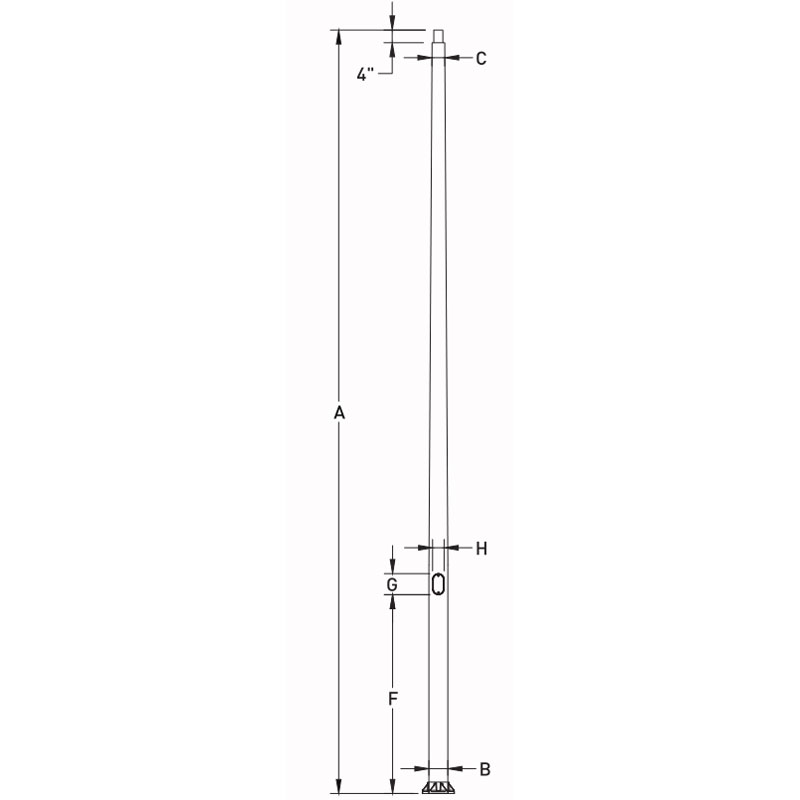 10-40ft Aluminum Conical Light Pole with Base FlangeThis extruded AL6063 pole, T6 heat-treated, offers base flange mounting for easy installation. Its multiple heights allow specifiers to match section modulus to site-specific wind loads per ASCE 7-10.View Product →
Morelux supplies conical aluminum poles for American projects in 10 to 40-foot heights, with base flange and direct burial options. These designs can be evaluated against the site-specific ASCE 7-10 wind speed during the quotation stage.
Aluminum versus Steel in Wind-Sensitive Projects
The radar chart below compares five design characteristics that matter when wind load controls the pole size.
The radar chart compares aluminum and steel light poles on five design characteristics that interact with wind performance. Aluminum shows a higher strength-to-weight ratio, which means the pole can be lighter while carrying similar moment capacity. Aluminum is also more resistant to corrosion, an advantage in coastal wind zones where salt spray accelerates damage. Steel tends to score higher on impact resistance and fatigue life under repeated strong gusts, especially when the pole has a heavier luminaire load. Neither material is uniformly better; the correct choice depends on the site wind speed, risk category, and lifecycle maintenance strategy. This is why a manufacturer that can supply both aluminum and steel poles is helpful when project wind loads vary across county lines.
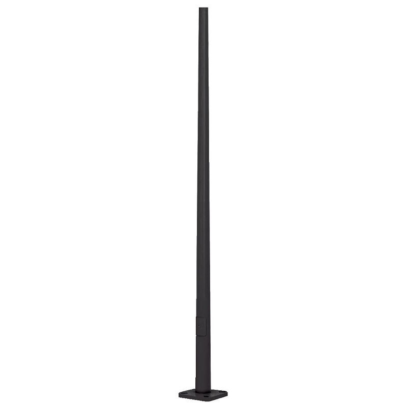 Round Tapered Steel Light Pole with Base FlangeMade from ASTM A500 Grade C steel with high yield strength, this tapered pole handles heavy luminaire loads and repeated wind gusts. Its 4-bolt flange and optional anchor kit support robust installations.View Product →
Practical Steps for Specifying a Pole Under ASCE 7-10
Follow this workflow to avoid under-specifying a pole. If you are unsure which wind speed applies, contact Morelux with the project address and building code edition.
- Identify the project Risk Category and building code edition.
- Read the design wind speed from the corresponding ASCE 7-10 map.
- Select the wind exposure category based on terrain.
- Compute the velocity pressure and the force coefficient.
- Compare the required base moment with the pole manufacturer's load tables.
- Verify the foundation and anchor bolt design with a professional engineer.
Once the design wind speed is known, compare the required base moment against manufacturer load tables. For a project where the wind speed map shows a high value, a larger conical aluminum pole or a steel pole may be needed. If you share the Risk Category, exposure, and basic wind speed with the supplier, the quotation can be more precise.
 10-40ft Aluminum Conical Light Pole, Direct BurialThis planted-mount aluminum pole features a flattened bottom to prevent rotation, with wire access 24 inches above ground. Ideal for projects requiring direct burial and flexible wind-load evaluation.View Product →
The Bottom Line: Match the Pole to the Map
The ASCE 7-10 wind speed map is not a single number that applies to every site. It depends on Risk Category, location, and the edition of the standard being used. Because wind pressure grows with the square of the speed, the difference between 90 mph and 130 mph is much greater than the raw numbers suggest. Specifiers should always record the exact Risk Category and basic wind speed used in the design. A trusted pole supplier will ask for these values before suggesting a product. For additional comparison of pole materials, read our review of steel light poles and the factors that make them the preferred choice for certain wind environments.