English
 Español
 Français
 عربى
عربى italiano
Choosing the right steel light pole comes down to six core factors: pole height, wall thickness and load capacity, steel grade, corrosion protection method, mounting configuration, and aesthetic requirements. Getting these right from the start ensures structural safety, minimizes lifecycle costs, and avoids costly replacements within the first decade of service. Steel light poles remain the dominant choice for urban roads, highways, parks, parking lots, and sports facilities worldwide — combining high mechanical strength, weldability for field repairs, long service life, and competitive cost per unit of illumination delivered.
The sections below walk through each selection criterion in practical detail, with data and comparison tables to support your decision-making process — whether you are specifying a single replacement pole or procuring hundreds for a large-scale infrastructure project.
Content
- 1 Determine the Required Pole Height First
- 2 Select the Correct Steel Grade and Wall Thickness
- 3 Assess Wind Load Requirements for the Installation Site
- 4 Choose the Right Corrosion Protection Method
- 5 Understand Pole Shape and Taper Options
- 6 Evaluate Arm and Bracket Configuration
- 7 Specify the Foundation and Anchor Bolt System Correctly
- 8 Consider Aesthetic Requirements and Urban Design Context
- 9 Factor in Smart City and Multifunctional Integration Requirements
- 10 Evaluate Total Cost of Ownership, Not Just Purchase Price
- 11 Steel Light Pole Selection Checklist
Determine the Required Pole Height First
Pole height is the primary specification that drives almost every other parameter — wall thickness, base diameter, anchor bolt pattern, and luminaire selection all scale with height. Selecting the wrong height leads to either under-illuminated areas or unnecessarily high structural and material costs.
As a general planning reference, the following height ranges are widely used across application types:
| Application | Typical Pole Height | Typical Spacing | Notes |
|---|---|---|---|
| Residential streets | 5–8 m | 20–35 m | Decorative styles common |
| Urban arterial roads | 8–12 m | 30–45 m | Single or double-arm bracket |
| Highways and expressways | 10–14 m | 40–60 m | High wind load design required |
| Parking lots | 6–10 m | 25–40 m | Multi-arm brackets reduce pole count |
| Sports fields and stadiums | 15–40 m | Varies by field size | High-mast configuration; multiple luminaires |
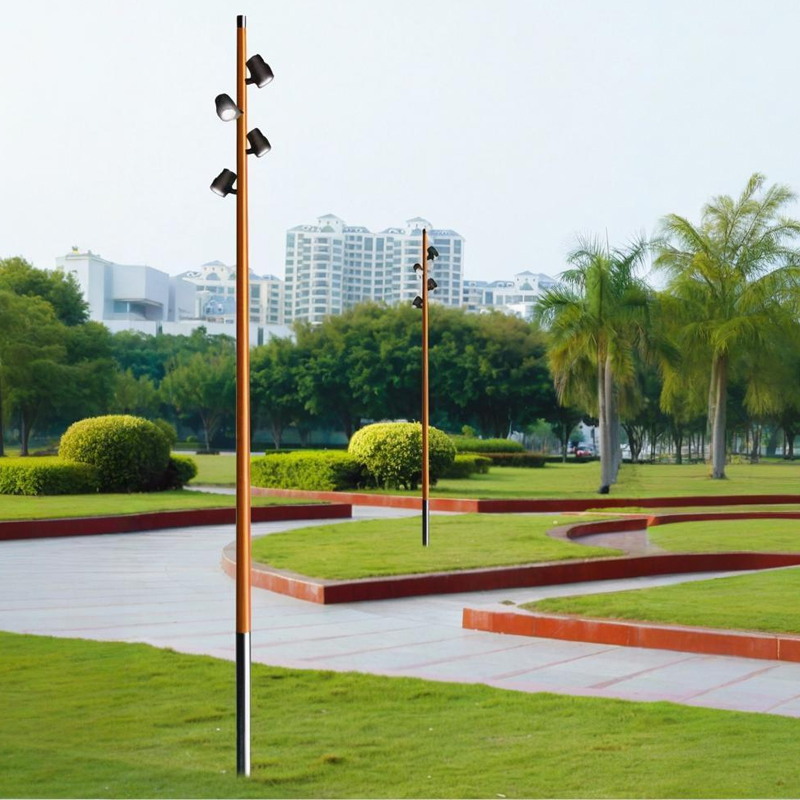
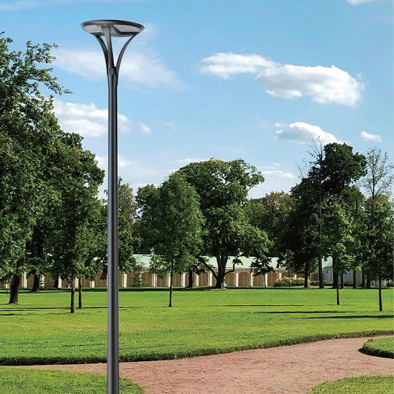
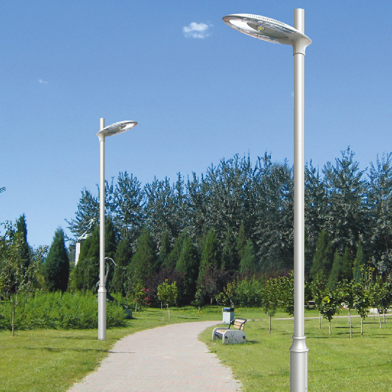
| Parks and pedestrian paths | 3–6 m | 15–25 m | Decorative bollard or scroll styles |
| Port and industrial areas | 20–45 m | Varies by site layout | High-mast; corrosion-resistant spec |
A widely applied rule of thumb is that the illuminated width of a roadway should be approximately 0.8 to 1.2 times the pole mounting height for uniform illumination with standard luminaires. For a 12-meter-wide two-lane road, an 8 to 10 meter pole will typically achieve the required uniformity ratio. Taller poles cover wider areas per luminaire but require higher-output light sources and more robust structural specifications.
Always verify local standards — many countries and municipalities publish specific road lighting standards (such as EN 13201 in Europe or IESNA RP-8 in North America) that define minimum maintained illuminance, uniformity, and glare limits for each road category, which in turn drive pole height and spacing calculations.
Select the Correct Steel Grade and Wall Thickness
Steel grade and wall thickness determine whether the pole can safely carry its own weight, the weight of luminaires and brackets, and the dynamic loads imposed by wind — the dominant structural challenge for tall, slender steel poles.
Common Steel Grades for Light Poles
Most steel light poles are fabricated from low-alloy structural steel. The three most common grades used globally are:
- Q235 (equivalent to ASTM A36): The most widely used general-purpose structural steel for poles up to approximately 10 meters. Yield strength of 235 MPa. Cost-effective and readily available. Suitable for moderate wind zones with standard luminaire loads.
- Q345 (equivalent to ASTM A572 Grade 50): Higher-strength steel with a yield strength of 345 MPa. Preferred for poles above 10 meters, high-wind-zone installations, and high-mast poles carrying multiple heavy luminaires. Allows thinner walls while maintaining structural safety margins.
- Q355 / S355: European-standard high-strength structural steel widely used in coastal and corrosive environments where both mechanical strength and weldability under challenging conditions are required. Yield strength of 355 MPa.
Wall Thickness Guidelines
Wall thickness must be specified in conjunction with pole height and taper ratio. Under-specifying wall thickness is one of the most common causes of structural failure in steel light poles, particularly in high-wind or high-luminaire-load applications. General industry guidelines for tapered steel poles are:
- Poles up to 6 m: minimum wall thickness of 3.0–3.5 mm
- Poles 6–10 m: minimum wall thickness of 3.5–4.5 mm
- Poles 10–14 m: minimum wall thickness of 4.5–6.0 mm
- High-mast poles 15–40 m: minimum wall thickness of 6.0–12.0 mm, verified by structural engineering calculation
Always request a structural calculation certificate from the supplier confirming that the specified wall thickness, taper, and base diameter comply with the wind loading requirements for the installation site. Reputable manufacturers will provide this documentation as standard.
Assess Wind Load Requirements for the Installation Site
Wind load is the primary dynamic force that steel light poles must resist throughout their service life. Specifying a pole that is not rated for the wind conditions at its installation site is a safety and liability issue, not merely a performance one. Structural failures of light poles during storms cause property damage, road hazards, and injury — and are largely preventable through correct specification.
Wind load calculations depend on three site-specific inputs:
- Basic wind speed: The 50-year return period design wind speed for the geographic location, typically specified in national or regional structural codes (e.g., ASCE 7 in the USA, EN 1991-1-4 in Europe, GB 50009 in China).
- Terrain and exposure category: Open coastal sites have significantly higher effective wind pressures than urban sites with dense building cover, even at the same basic wind speed. Exposure categories A through D (or equivalent) adjust the design wind pressure accordingly.
- Luminaire drag area: The projected area and drag coefficient of all luminaires, brackets, and attachments mounted on the pole. A dual-arm bracket with two large LED road luminaires can add 30–50% to the effective wind load compared to a bare pole top.
For coastal regions, typhoon-prone areas, or open terrain sites, always specify poles rated for wind speeds at least 10–15% above the regional basic wind speed as a safety buffer. In many tropical coastal regions, design wind speeds of 45–55 m/s are appropriate, requiring significantly heavier-gauge poles than those typically supplied for inland urban applications.
Choose the Right Corrosion Protection Method
Steel is susceptible to corrosion, and the corrosion protection system applied to a light pole is the single biggest determinant of how long the pole remains structurally sound and visually acceptable without major maintenance intervention. Selecting the appropriate anti-corrosion treatment for the deployment environment can extend pole service life by 10 to 20 years compared to using an inadequate protection system.
Hot-Dip Galvanizing
Hot-dip galvanizing (HDG) is the most widely specified corrosion protection for steel light poles globally, and for good reason. The process immerses the fabricated pole in a bath of molten zinc at approximately 450°C, creating a metallurgically bonded zinc-iron alloy coating that covers all internal and external surfaces — including welds, cut edges, and interior conduit surfaces that paint systems cannot reach.
- Minimum coating thickness for street furniture per ISO 1461: 85 μm for steel sections above 6 mm wall thickness
- Expected service life in inland urban environments: 20–30 years before first maintenance is required
- Self-healing property: zinc sacrificially protects exposed steel at cut edges or minor surface damage without requiring touch-up
- Compatible with powder coat or wet paint overcoat for additional protection or color specification
Hot-Dip Galvanizing Plus Powder Coating (Duplex System)
For coastal environments, industrial zones, or any application requiring a specific color finish, the duplex system — HDG base coat plus a powder coat or two-pack polyurethane topcoat — offers substantially superior protection. The combined system provides 1.5 to 2.5 times the corrosion protection life of HDG alone in aggressive environments, and delivers the color consistency required for aesthetically sensitive urban installations. Powder coat thickness of 60–80 μm over a zinc base is typical.
Electro-Galvanizing and Paint Systems
Electro-galvanized or zinc-spray coatings with paint topcoats are sometimes offered as a lower-cost alternative. These systems provide significantly thinner zinc coverage (typically 8–25 μm) and are not recommended for outdoor street lighting applications where long service life is required. They are appropriate only for indoor or very sheltered applications where aesthetic appearance rather than corrosion protection is the primary goal of the coating system.
Weathering Steel (Corten)
Weathering steel (COR-TEN or equivalent) forms a stable, adherent rust patina that inhibits further corrosion without painting or galvanizing. It is used for architectural and landscape lighting poles where the warm brown oxidized appearance is a deliberate design choice. Weathering steel poles are not appropriate for marine environments or locations with frequent wet-dry cycling, where the protective patina may not form uniformly.
Understand Pole Shape and Taper Options
Steel light poles are available in several cross-sectional shapes and taper configurations, each with different structural, aesthetic, and manufacturing cost implications.
| Shape | Cross Section | Structural Efficiency | Typical Application | Aesthetic Character |
|---|---|---|---|---|
| Round tapered | Circular, reduces toward top | High — uniform stress distribution | Roads, highways, parking | Clean, modern, utilitarian |
| Straight round | Uniform circular diameter | Moderate — heavier than tapered | Decorative urban, parks | Classic, architectural |
| Octagonal tapered | Eight-sided, reduces toward top | High — good bending resistance | Highways, high-mast | Angular, industrial |
| Decorative fluted | Round with vertical flute profiles | Moderate | Heritage districts, plazas | Classical, ornamental |
| Square tapered | Four-sided, reduces toward top | Moderate — directionally variable | Plazas, architectural projects | Contemporary, geometric |
Round tapered poles are the most structurally efficient shape for a given material weight, as the circular cross-section provides equal bending resistance in all directions — important for a pole that may experience wind from any direction. Octagonal poles offer similar efficiency with a more angular aesthetic that is widely used on highways. Decorative shapes are appropriate where visual character is a priority, provided the structural specification is not compromised to achieve the aesthetic.
Evaluate Arm and Bracket Configuration
The luminaire arm or bracket extends the light source horizontally from the pole, determining the relationship between pole position, luminaire overhang over the road, and the illumination distribution pattern. Arm configuration significantly affects both the lighting performance and the structural load on the pole.
Single Arm
A single outreach arm extending 1 to 3 meters from the pole is the most common configuration for roadside poles. The arm projects the luminaire over the carriageway, reducing the number of poles needed for a given road width. Typical arm outreach is 1 to 2.5 meters for roads up to 12 meters wide, and 2 to 4 meters for wider dual-carriageway roads. Longer arms increase the bending moment at the arm-to-pole connection, requiring heavier arm wall thickness and reinforced mounting brackets.
Double Arm
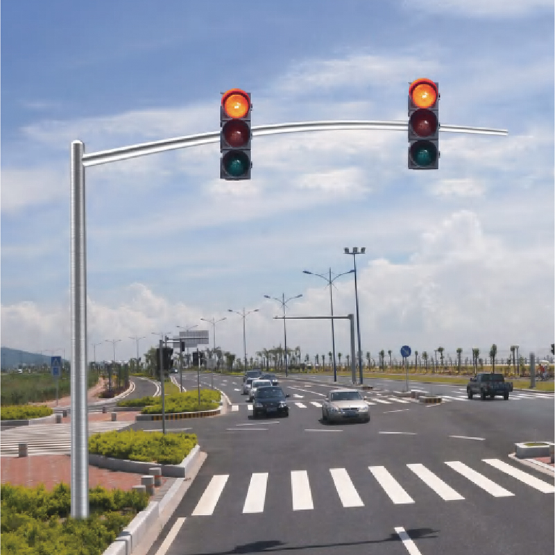
Twin arms extending in opposite directions allow a single pole positioned at the road centerline or median to illuminate both sides of a dual carriageway — reducing pole count and installation cost by up to 40% compared to single-arm poles on both sides of the road. Wind loads from double-arm configurations must be carefully analyzed, as the effective drag area is significantly greater than a single-arm pole.
Multi-Arm for High-Mast Applications
High-mast poles (15 meters and above) typically use a ring-mounted luminaire assembly carrying 4 to 12 luminaires pointing outward and downward from a central ring at the pole top. Lowering gear mechanisms allow the entire luminaire ring to be descended to ground level for maintenance — an essential feature for poles above 20 meters where working at height on a ladder or elevated platform becomes impractical.
Specify the Foundation and Anchor Bolt System Correctly
A steel light pole is only as stable as its foundation. More structural failures of light poles occur at or below ground level than in the pole shaft itself — primarily due to inadequate foundation depth, anchor bolt corrosion, or poor concrete quality. Correct foundation specification is not optional; it is the basis of the entire structural system.
Key foundation specification parameters include:
- Foundation depth: Typically 10–15% of the above-ground pole height, plus a minimum depth below the frost line in cold climates. An 8-meter pole generally requires a foundation depth of 1.0 to 1.2 meters; a 12-meter pole requires 1.4 to 1.8 meters.
- Anchor bolt grade and diameter: Most pole foundations use 4 or 6 anchor bolts of Grade 4.8 or 8.8 steel in configurations matching the pole base plate. Bolt diameter typically ranges from M20 to M48 depending on pole height and wind loading. All anchor bolts and exposed hardware should be hot-dip galvanized to the same standard as the pole.
- Concrete specification: A minimum compressive strength of C25/30 (25 MPa cylinder / 30 MPa cube) is standard for street lighting foundations. Higher strengths are required for high-mast foundations or poor-bearing-capacity soils.
- Base plate and leveling nut provision: The pole base plate must match the anchor bolt circle diameter precisely. Double-nut installation with leveling nuts allows precise vertical alignment during installation and should be specified for all poles above 8 meters.
- Conduit entry sealing: All cable entry points at the foundation level should be sealed against water ingress, as ground-level moisture is the primary cause of internal pole corrosion in hot-dip galvanized poles.
Consider Aesthetic Requirements and Urban Design Context
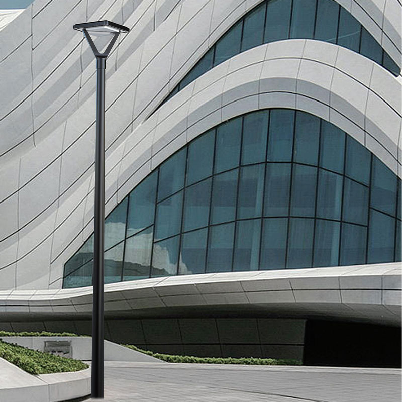
Steel light poles are not purely functional structures — in most urban environments they are visible elements of the streetscape that contribute to the visual identity of a district, neighborhood, or development. Integrating the aesthetic specification of the light pole with the urban design framework from the beginning of a project avoids costly retrospective changes and ensures a cohesive public realm.
Key aesthetic considerations include:
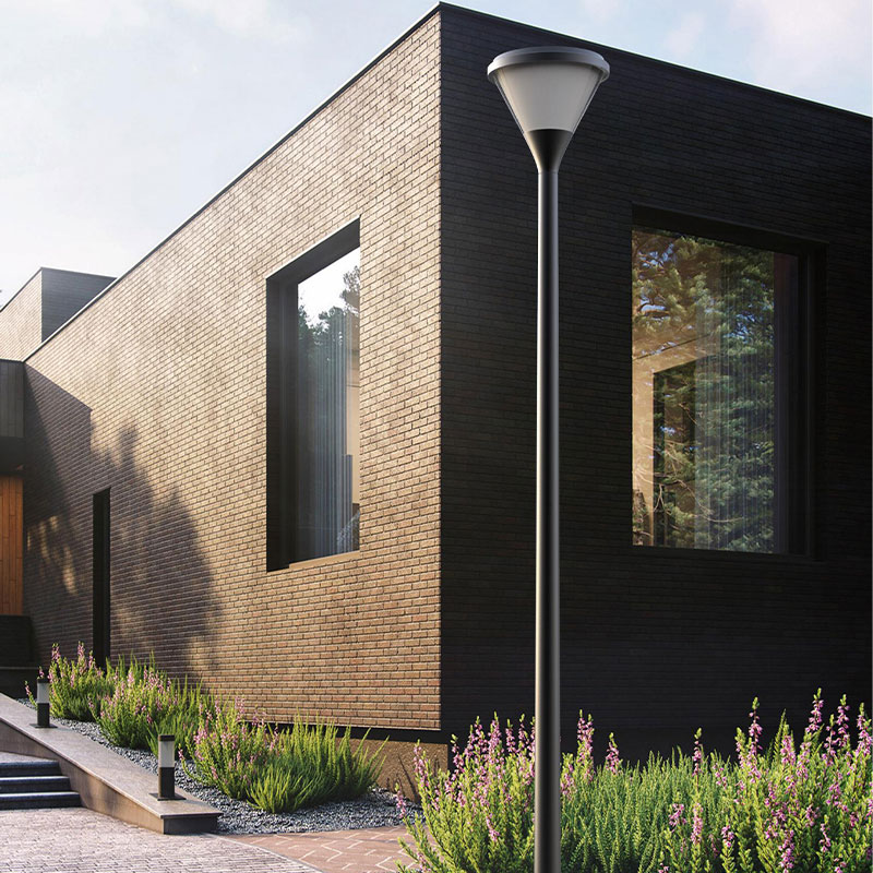
- Color and finish: RAL powder coat colors allow poles to be specified in virtually any color to complement building facades, streetscape materials, or brand palettes. Common urban choices include RAL 7016 anthracite grey, RAL 9005 jet black, and RAL 6009 fir green for heritage areas. Custom colors are available from most manufacturers with a minimum order quantity.
- Decorative details: Cast iron or steel base ornaments, scroll arms, ball finials, and fluted shaft profiles are widely available for heritage, civic, and high-end commercial applications. These elements add cost — typically 20 to 50% above a plain tapered pole equivalent — but deliver lasting visual character that plain industrial poles cannot.
- Consistency across the project: Using a single pole family (same profile, color, and arm style) throughout a project creates visual cohesion. Mixing pole styles in a single streetscape or development typically produces an incoherent result that diminishes the quality of the public realm.
- Luminaire and pole visual integration: The proportions of the luminaire head should complement the pole style. A sleek, flat LED road luminaire suits a plain tapered pole; a more voluminous traditional lantern suits a fluted decorative pole. Mismatching styles reduces the visual quality of both elements.
Factor in Smart City and Multifunctional Integration Requirements
If the project involves smart city functionality — surveillance cameras, environmental sensors, 5G small cells, digital displays, Wi-Fi access points, or EV charging — the pole specification must account for these additional loads and infrastructure requirements from the outset. Retrofitting smart equipment onto poles not designed for it is significantly more expensive and often structurally compromised compared to designing for it initially.
For multifunctional smart poles, the specification should address:
- Increased wall thickness and base diameter to accommodate the additional wind load from cameras, sensor housings, display screens, and communication antenna arrays.
- Integrated cable management ducting with sufficient internal diameter to route power, data, and communication cables to multiple mounting positions along the pole height.
- Lockable technology cabinets at the pole base for housing controllers, communication hardware, power distribution units, and network switches.
- Standardized mounting interfaces — rail systems, threaded inserts, or bracket attachment points — at specified heights along the pole to accommodate current and future smart equipment additions.
- Power supply capacity sufficient for all current and planned future loads, including allowance for EV charging point power (typically 3.5 to 22 kW per outlet) if charging is part of the scope.
A smart-ready steel pole specified at the design stage typically adds 15 to 30% to the per-pole cost compared to a standard lighting pole. However, this premium is far smaller than the cost of structural replacement or major retrofitting when smart city functionality is added later — making upfront specification the clearly more economical approach for any project with a 15 to 20-year planning horizon.
Evaluate Total Cost of Ownership, Not Just Purchase Price
The purchase price of a steel light pole is rarely the most significant cost over its service life. Installation, foundation, luminaire, electrical connection, maintenance, and eventual replacement costs typically exceed the pole purchase price several times over across a 20 to 25-year lifecycle. Choosing a pole solely on the basis of the lowest unit price frequently produces the highest total lifecycle cost.
A realistic total cost of ownership analysis should include:
- Foundation cost: Typically $150 to $600 per pole depending on depth, soil conditions, and local labor rates — often exceeding the pole unit cost for smaller poles.
- Installation labor: Crane time, crew, traffic management, and backfill can add $200 to $800 per pole in urban installations.
- Maintenance frequency: A properly galvanized steel pole in a moderate environment requires minimal maintenance for 15 to 20 years. A lower-cost paint-finished pole may need recoating every 5 to 8 years, at $100 to $300 per pole per cycle.
- Repairability: One of the most cost-effective advantages of steel over composite or concrete poles is that damaged steel poles can be welded and repaired on-site or replaced section by section. A vehicle impact that destroys a composite pole requiring full replacement may only require a partial section replacement or weld repair on a steel pole — saving $500 to $2,000 per incident.
- End-of-life scrap value: Steel poles have positive scrap value at end of life, unlike composite or concrete alternatives. This is a minor but real financial offset to consider in long-horizon lifecycle calculations.
Steel light poles consistently deliver the best combination of structural performance, repairability, longevity, and cost-effectiveness across the broadest range of application types — from quiet residential streets to major highway interchanges — when correctly specified for the site conditions and designed with appropriate corrosion protection from the outset.
Steel Light Pole Selection Checklist
Use the following checklist to ensure all critical specification decisions have been addressed before finalizing a steel light pole order:
- Determine required pole height based on road width, illuminance standard, and luminaire type.
- Confirm local wind speed zone and terrain category; obtain design wind speed from applicable structural code.
- Select steel grade (Q235, Q345, Q355, or equivalent) appropriate to pole height and wind load.
- Specify minimum wall thickness verified by structural calculation for the design wind speed and luminaire load.
- Choose corrosion protection system (HDG only, or duplex HDG + powder coat) based on environmental aggressiveness.
- Select pole shape (round tapered, octagonal, decorative) aligned with functional requirements and urban design context.
- Define arm configuration (single, double, multi-arm) and confirm arm outreach does not create unacceptable bending loads.
- Specify foundation depth, anchor bolt size and grade, and concrete strength based on site soil conditions and pole loading.
- Confirm color and finish specification, including RAL color code if powder coat is required.
- Address smart city integration requirements (cable ducting, technology cabinet, additional structural load allowance) if applicable.
- Request structural calculation certificate and quality compliance documentation from the manufacturer before order confirmation.