English
 Español
 Français
 عربى
عربى italiano
Solar light poles work by collecting sunlight through a photovoltaic (PV) panel mounted on or near the pole, converting that sunlight into direct current (DC) electricity, storing the energy in a rechargeable battery system housed within the pole structure, and then automatically discharging that stored energy through a charge controller to power an LED luminaire during the hours of darkness. The entire system is self-contained and operates completely independently of the utility grid — no underground power cables, no connection to the mains supply, and no ongoing electricity cost. A light-sensitive photocell or programmable timer built into the charge controller triggers the LED luminaire to switch on automatically at dusk and switch off at dawn, repeating this cycle each day using only the solar energy harvested the previous day. Understanding how each component in this energy chain functions, and how the components interact with one another, explains both the significant advantages solar light poles offer and the practical limitations that must be accounted for when specifying them for any given installation.
Content
- 1 The Five Core Components That Make Solar Light Poles Function
- 2 The Energy Flow Through a Solar Light Pole: Step by Step
- 3 How Solar Light Poles Are Configured: Integrated vs. Split Systems
- 4 How Solar Light Pole Performance Is Calculated and Specified
- 5 Advantages of Solar Light Poles Over Grid-Connected Street Lighting
- 6 Limitations of Solar Light Poles and How They Are Managed
- 7 Key Specifications to Evaluate When Selecting Solar Light Poles
- 8 Typical Applications Where Solar Light Poles Deliver Best Results
The Five Core Components That Make Solar Light Poles Function
Every solar light pole, regardless of size or application, relies on the same five functional elements working in sequence. The performance of the complete system is determined by how well each component is specified for the local solar resource, the required lighting output, and the nights of autonomy needed between sunny days.
Component 1: The Photovoltaic Solar Panel
The solar panel is the energy collection device. It consists of an array of photovoltaic cells — typically monocrystalline or polycrystalline silicon — that convert photons of light directly into electrical current through the photovoltaic effect, first demonstrated experimentally by Edmond Becquerel in 1839 and now described by established semiconductor physics. When photons strike the semiconductor junction within each PV cell, they excite electrons across the junction, generating a small voltage and current. Individual cells are wired in series and parallel combinations to produce the panel's rated voltage and power output.
Monocrystalline silicon panels, the most common choice for solar light pole applications, achieve conversion efficiencies of 17 to 23% under standard test conditions (STC: 1,000 W/m2 irradiance, 25 degrees Celsius cell temperature). In real-world outdoor conditions, effective efficiency is typically 10 to 15% lower than the STC rating because cell temperature rises above 25 degrees Celsius in direct sunlight, reducing efficiency by approximately 0.4 to 0.5% per degree Celsius above the reference temperature (Source: IEC 61215, Terrestrial Photovoltaic Modules — Design Qualification and Type Approval).
Panel wattage for solar light poles is sized based on the daily energy required by the LED luminaire, the peak sun hours available at the installation location, the battery storage capacity, and the desired number of consecutive cloudy-day autonomy nights. A solar light pole requiring a 30-watt LED to run for 10 hours per night at a location with 4 peak sun hours per day requires a panel capable of generating at least 300 watt-hours of energy per day — meaning a panel rated at roughly 80 to 100 watts at STC after accounting for real-world efficiency losses and system losses in the charge controller and battery.
Component 2: The Charge Controller
The charge controller is the intelligence unit of the solar light pole system. It sits between the solar panel, the battery, and the luminaire, managing the flow of current to protect the battery from overcharge and deep discharge while also controlling the luminaire's operating schedule and, in advanced systems, its brightness level.
Two charge controller technologies are in common use in solar street lighting systems:
- PWM (Pulse Width Modulation) controllers: Connect the solar panel directly to the battery and regulate charging by rapidly switching the charge current on and off, reducing the average current as the battery approaches full charge. PWM controllers are simple, reliable, and cost-effective, but they do not extract the maximum available power from the panel because the panel is forced to operate at battery voltage rather than at its own optimum voltage (the maximum power point)
- MPPT (Maximum Power Point Tracking) controllers: Use DC-DC conversion circuitry to continuously find and maintain the solar panel's maximum power point — the combination of voltage and current at which the panel produces the greatest power output for a given irradiance level. MPPT controllers can harvest 10 to 30% more energy from the same panel compared to PWM controllers, particularly at low irradiance levels (early morning, late afternoon, overcast conditions) and in cold climates where panel voltage rises above battery voltage by a greater margin (Source: NREL Technical Report, Comparison of MPPT and PWM Charge Controllers, National Renewable Energy Laboratory)
The charge controller also implements the dusk-to-dawn switching function through either a photocell sensor or a programmable timer, and in most modern systems supports dimming profiles that reduce LED output during late-night hours when pedestrian traffic is minimal — extending the available battery energy to cover more hours of operation or more consecutive cloudy nights.
Component 3: The Battery Storage System
The battery is the energy reservoir that bridges the gap between solar energy collection (daylight hours) and energy consumption (nighttime hours). Battery specification is one of the most consequential decisions in solar light pole system design, directly affecting system autonomy, operational lifespan, and total lifecycle cost.
Three battery chemistries are used in solar street lighting applications:
- Sealed lead-acid (SLA/AGM/GEL): The oldest and lowest-cost technology, with energy density of approximately 30 to 50 Wh/kg. Reliable and well-understood, but heavy, sensitive to deep discharge (which permanently reduces capacity), and limited to approximately 300 to 500 full charge-discharge cycles at 80% depth of discharge before capacity falls below 80% of original
- Lithium iron phosphate (LiFePO4): Now the most widely specified chemistry for quality solar light poles, offering energy density of 90 to 160 Wh/kg, tolerance of deep discharge without permanent damage, and cycle life of 1,500 to 3,000 full cycles at 80% DoD before reaching 80% capacity — roughly 4 to 8 times longer than lead-acid (Source: Battery University, BU-205, Types of Lithium-ion, Cadex Electronics)
- Lithium NMC (Nickel Manganese Cobalt): Higher energy density than LiFePO4 but less thermally stable at high temperatures and with somewhat shorter cycle life; used in some integrated all-in-one solar street light designs where minimizing physical size is a priority
Battery capacity is specified in watt-hours (Wh) or ampere-hours (Ah at the nominal voltage) and must be sized to provide the required number of autonomy nights — the consecutive cloudy nights during which the system must operate at its specified output without any solar recharging. Most municipal and road lighting specifications require a minimum of 3 to 5 consecutive nights of autonomy, requiring battery capacity of 3 to 5 times the daily energy consumption of the luminaire and control system.
Component 4: The LED Luminaire
The LED luminaire is the light-producing device, converting the DC electrical energy discharged from the battery into visible light to illuminate the road, pathway, or area below the pole. LEDs (Light Emitting Diodes) are the universal choice for solar street lighting applications because of their combination of high luminous efficacy, long operational lifespan, and compatibility with DC power supply — properties that make them uniquely suited to the constraints of battery-powered operation.
Quality LED luminaires for solar street lighting applications achieve luminous efficacy values of 130 to 180 lumens per watt or higher, dramatically reducing the electrical energy demand per unit of light output compared to any legacy light source. This high efficacy is central to the economics of solar street lighting — every watt of LED efficacy improvement directly reduces the required panel wattage and battery capacity, and therefore the total system cost.
LED street lighting luminaires for solar applications incorporate optical systems designed to distribute light efficiently over the target illumination area — typically the road surface below and immediately around the pole — using asymmetric lens or reflector arrangements that minimize wasted light directed upward (light pollution) or beyond the useful illumination zone. The photometric distribution must be matched to the pole height and spacing to achieve the target illuminance levels specified in road lighting standards such as EN 13201 (European road lighting standard) or IESNA RP-8 (North American standard) for the road classification concerned.
Component 5: The Pole Structure
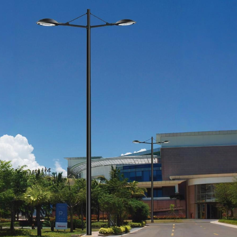
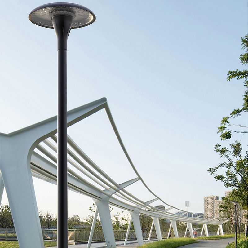
The pole provides the structural support to mount the PV panel at the optimal height and tilt angle for solar collection, positions the luminaire at the designed mounting height for the required illuminance distribution, and in most integrated designs also houses the battery and charge controller within a sealed compartment in the pole base or mid-section.
Solar light poles are typically manufactured in steel (hot-dip galvanized and powder-coated) or aluminum alloy, with heights ranging from 4 metres for pathway and garden applications to 12 metres or more for road and highway lighting applications. The structural design must account for the combined wind loading of both the luminaire and the PV panel mounted at the top of the pole, which together create a significant sail area and bending moment at the pole base in storm conditions.
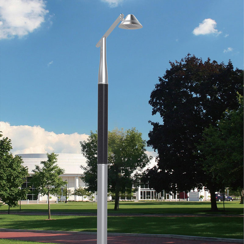
Premium quality Solar Light Poles from manufacturers serving the European and Middle Eastern markets integrate all five system components into a coherent, aesthetically refined design — with the PV panel, luminaire, battery compartment, and charge controller specified as a matched system optimized for the solar resource and road lighting requirements of the target region.
The Energy Flow Through a Solar Light Pole: Step by Step
Understanding the moment-by-moment energy flow through a solar light pole system helps clarify how each component affects overall performance and reliability.
Daytime: Solar Collection and Battery Charging
From sunrise, photons of sunlight strike the PV panel cells and generate DC current, which flows through the positive and negative leads to the charge controller. The charge controller immediately begins directing this current to the battery, following a multi-stage charging profile:
- Bulk charge phase: Maximum available current from the panel flows into the battery, rapidly increasing state of charge (SoC). Battery voltage rises steadily. This phase continues until the battery reaches approximately 80% of full charge
- Absorption phase: The charge controller holds battery voltage at the absorption setpoint (for LiFePO4, approximately 14.4 to 14.6V for a 12V nominal battery) and allows current to taper naturally as the battery approaches full charge
- Float phase: Once the battery is fully charged, the controller reduces voltage to the float setpoint to maintain full charge without overcharging, dissipating only the self-discharge current of the battery
On a clear day at a well-sited location, the battery typically reaches full charge by early to mid-afternoon, after which the solar panel's output is curtailed by the charge controller to prevent overcharge. Any energy generated by the panel after the battery is full is not stored — which is why accurate battery sizing is important for maximizing the proportion of available solar energy that is actually captured and used.
Dusk: Automatic Luminaire Activation
As ambient light levels fall at dusk, the photocell sensor on the charge controller detects the reduction in light intensity. Most controllers use a threshold typically corresponding to an illuminance level of 10 to 30 lux at the sensor surface to trigger the switch-on command. At this threshold, the charge controller activates the DC output circuit to the LED luminaire driver, and the luminaire illuminates at its programmed initial output level.
A timer-based fallback is typically programmed alongside the photocell, ensuring the light switches on at a defined time after sunset even if the photocell is temporarily obstructed (by a bird, leaf, or accumulated debris) and the photocell trigger does not fire correctly.
Nighttime: Battery Discharge and Dimming Profiles
Through the night, the battery steadily discharges to power the LED luminaire and charge controller electronics. The charge controller monitors battery voltage (or state of charge in advanced systems using Coulomb counting) and implements pre-programmed dimming profiles to manage energy consumption across the night.
A typical dimming profile for a solar street light on a residential road might operate as follows:
- Dusk to 11:00 PM: 100% output — peak pedestrian and vehicle activity, maximum illuminance required
- 11:00 PM to 5:00 AM: 50% output — reduced traffic volume allows reduced illuminance while maintaining basic safety requirements; energy consumption halved
- 5:00 AM to dawn: 100% output — morning commuter activity resumes, full illuminance restored
This dimming profile reduces total nightly energy consumption by approximately 35 to 40% compared to full-output all-night operation, proportionally increasing the number of consecutive cloudy nights the battery can support before charge is depleted. Motion-sensing variants add an additional layer of intelligence: the luminaire dims further (to 20 to 30% output) during periods of no detected movement, brightening to full output only when a pedestrian or vehicle enters the detection zone.
Dawn: Luminaire Shutdown and Charging Recommences
At dawn, the photocell detects rising ambient light above the switch-off threshold and signals the charge controller to cut the DC output to the luminaire. Simultaneously, as solar irradiance rises with the sun, the panel begins generating current again and the charge controller recommences the battery charging cycle. On a clear day following a full night of operation, a correctly sized system will return the battery to full charge well before midday.
How Solar Light Poles Are Configured: Integrated vs. Split Systems
Solar light poles are manufactured in two primary physical configurations, each with distinct advantages suited to different applications and site conditions.
Integrated (All-in-One) Solar Light Poles
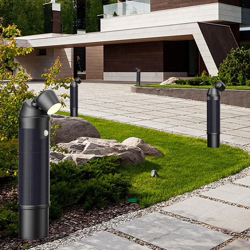
In an integrated design, the solar panel, LED luminaire, battery, and charge controller are combined into a single compact assembly mounted at the top of the pole. This configuration minimizes the number of individual components and external connections, simplifying installation and reducing the number of potential points of failure.
The panel in an all-in-one design is typically fixed in a horizontal or near-horizontal orientation, since the assembly must be compact enough to integrate cleanly with the luminaire body. This limits the panel area and therefore the maximum system power, making all-in-one designs best suited to lower-power applications such as pathway lighting, parking area lighting, and residential street lighting where luminaire wattages of 10 to 40 watts are appropriate.
The battery in most all-in-one designs is a lithium pack integrated into the luminaire housing. This placement means the battery operates at or near ambient air temperature, which affects performance and longevity in extreme climates — lithium batteries lose capacity significantly at temperatures below 0 degrees Celsius and experience accelerated aging at temperatures consistently above 45 degrees Celsius.
Split (Component) Solar Light Poles
In a split configuration, the solar panel is mounted separately — either on a dedicated mounting arm at the top of the pole or on a ground-mounted array near the pole — while the LED luminaire is mounted independently, and the battery and charge controller are housed in a sealed compartment within the pole base. This separation allows each component to be optimally positioned and specified.
The separate panel mounting allows the panel to be tilted and oriented for maximum solar harvest — typically tilted at an angle equal to the local latitude and oriented due south (in the northern hemisphere) or due north (in the southern hemisphere). This orientation optimization can increase annual energy harvest by 10 to 25% compared to a horizontal panel at the same location, depending on latitude (Source: European Commission, PVGIS Solar Radiation Database, pvgis.ec.europa.eu).
The battery in a split system, housed in the shaded pole base compartment, benefits from significantly more stable thermal conditions than a battery integrated into a luminaire body exposed to direct sun. In hot-climate applications such as the Middle East, where daytime ambient temperatures regularly exceed 45 degrees Celsius, the thermal shielding provided by a well-designed pole base compartment can extend battery life by a factor of 2 to 3 compared to an unshielded all-in-one design operating in the same environment.
How Solar Light Pole Performance Is Calculated and Specified
Correct system sizing is the fundamental engineering task in solar light pole specification. An undersized system will fail to provide the specified illumination for the required number of consecutive cloudy nights; an oversized system wastes capital on panel and battery capacity that is never fully utilized.
Peak Sun Hours: The Key Location Variable
The number of peak sun hours (PSH) at a location is the single most important variable in solar light pole sizing. PSH is defined as the number of hours per day during which the average solar irradiance equals 1,000 W/m2 — the standard test condition irradiance for PV panels. It is calculated from the total daily solar irradiance (in Wh/m2) divided by 1,000 W/m2.
PSH values vary enormously by location and season. Representative annual average PSH values for selected locations worldwide illustrate the geographic variation that sizing calculations must account for:
| Location | Annual Average PSH (hrs/day) | Worst Month PSH (hrs/day) | Climate Type |
|---|---|---|---|
| Dubai, UAE | 5.8 to 6.2 | 4.5 (December) | Desert, very high solar resource |
| Riyadh, Saudi Arabia | 5.5 to 6.0 | 4.3 (December) | Desert, very high solar resource |
| Madrid, Spain | 4.8 to 5.3 | 2.8 (December) | Mediterranean, good solar resource |
| Rome, Italy | 4.5 to 5.0 | 2.5 (December) | Mediterranean, good solar resource |
| London, United Kingdom | 2.8 to 3.2 | 0.8 to 1.0 (December) | Temperate maritime, low winter resource |
| Lagos, Nigeria | 4.5 to 5.2 | 3.5 (August, rainy season) | Tropical, seasonal cloud variation |
| Mumbai, India | 5.0 to 5.5 | 3.0 (July, monsoon) | Tropical, monsoon seasonal variation |
| Source: European Commission Joint Research Centre, PVGIS Solar Radiation Database (pvgis.ec.europa.eu); NASA Surface Meteorology and Solar Energy Dataset | |||
Critically, solar light pole systems must be sized for the worst-month PSH value at the installation location, not the annual average — because it is in the month with the lowest solar irradiance that the system is most stressed, and it is during this month that the balance between daily energy harvest and daily energy consumption is tightest. A system sized for the annual average PSH will reliably fail to maintain the specified lighting performance during the worst month of the year.
Simplified Sizing Example
Consider a solar light pole installation in Dubai (worst-month PSH of 4.5 hours/day) requiring a 30W LED luminaire running for 10 hours per night, with a requirement for 3 consecutive nights of autonomy at 80% depth of discharge (DoD) using a LiFePO4 battery:
- Daily energy required by luminaire: 30W x 10 hours = 300 Wh per night
- Battery capacity required (3 nights autonomy at 80% DoD): (300 Wh x 3) / 0.80 = 1,125 Wh minimum battery capacity
- Daily panel energy required (accounting for 80% combined system efficiency): 300 Wh / 0.80 = 375 Wh from panel per day
- Panel wattage required: 375 Wh / 4.5 peak sun hours = 83 W minimum panel rating at STC
- Practical selection: 100W panel (next standard size above calculated minimum) with a 1,200 Wh LiFePO4 battery pack
Advantages of Solar Light Poles Over Grid-Connected Street Lighting
The functional independence of solar light poles from the electrical grid translates into a range of practical advantages that explain their rapid adoption in both developing and developed markets.
Elimination of Underground Cable Infrastructure
Conventional grid-connected street lighting requires the installation of underground armored cable from a power distribution point to each pole along the route, typically at a depth of 450 to 600 mm or more. The cost of cable trenching, conduit, cable itself, and connection to the distribution network commonly represents 50 to 70% of the total installed cost of a conventional street lighting project, and in areas with rock, high water tables, or existing underground services can be considerably higher (Source: UK Highways Agency, Street Lighting Design Manual, HD 67/11).
Solar light poles require no underground electrical connection at all — only a simple foundation and ground anchor. This eliminates the trench, cable, connection hardware, and the skilled electrical labor required for the underground work, dramatically reducing total installed project cost in most locations and enabling installation timelines measured in days rather than weeks.
Operation in Locations Without Grid Access
Solar light poles are inherently suitable for remote locations where grid electricity is unavailable or prohibitively expensive to supply — rural roads, agricultural access routes, mining access roads, development project sites, and areas where infrastructure development is ongoing. In many developing countries across Africa, Asia, and the Middle East, solar street lighting is the only economically viable technology for providing road lighting outside urban grid-connected areas.
Zero Ongoing Electricity Cost
Once installed, a solar light pole generates no electricity bills. In locations with high electricity tariffs, this zero operating energy cost translates into substantial savings over the 15 to 25-year service life of the installation. In European markets with industrial electricity tariffs, a conventional street light consuming 50 to 100 watts at current tariff rates accumulates an energy cost over 20 years that can equal or exceed the original capital cost of the installation.
Resilience During Grid Power Outages
Solar light poles with adequate battery reserves continue operating through grid power outages that darken conventional street lighting. This advantage is particularly significant in areas subject to frequent load shedding, storm damage to grid infrastructure, or grid supply disruptions for any reason — the solar poles are entirely unaffected by grid failure and continue to illuminate roads and public spaces normally throughout the outage period.
Reduced Carbon Footprint
Solar light poles generate their operating electricity from photovoltaic conversion of sunlight — a zero-carbon energy source during operation. In grid-connected lighting systems powered by electricity grids with significant fossil fuel generation, each luminaire is responsible for indirect CO2 emissions proportional to the grid's carbon intensity. A 50-watt conventional street light running 10 hours per night in a country with a grid carbon intensity of 300 gCO2/kWh generates approximately 55 kg of CO2 equivalent per year — which a solar replacement entirely eliminates from ongoing operations (Source: IEA, CO2 Emissions from Fuel Combustion, International Energy Agency, 2023).
Limitations of Solar Light Poles and How They Are Managed
Solar light poles have genuine limitations that must be honestly assessed and managed in system specification to avoid installations that underperform their design intent.
Dependence on Solar Resource Availability
The fundamental limitation of any solar energy system is its dependence on sunlight — which is variable by nature. Extended periods of cloud cover, heavy rainfall, dust storms (particularly relevant in the Middle East and North Africa), and winter months at higher latitudes can reduce solar energy harvest well below the design average for days or weeks at a time.
The system must be designed with sufficient battery autonomy to bridge these periods of reduced harvest without interrupting the lighting service. At high latitudes (above approximately 50 degrees north or south), winter day length and solar elevation angle combine to reduce available solar energy so dramatically that solar street lighting becomes economically impractical without very large panel and battery systems. At latitude 52 degrees north (London), the December average PSH of approximately 0.8 hours/day means a system would need a panel five to six times larger than one serving the same luminaire in Dubai during December — often making the total system cost uncompetitive with grid-connected alternatives even after eliminating cable costs.
Battery Degradation Over Time
All rechargeable batteries degrade with each charge-discharge cycle, and this degradation limits the effective service life of the battery component. LiFePO4 batteries, the best-performing chemistry for solar street lighting, typically retain 80% of their original capacity after 2,000 full cycles — approximately 5.5 years of daily cycling. At this point the battery may need replacement to maintain the original autonomy specification, representing a maintenance cost that must be accounted for in total lifecycle cost calculations (Source: Battery University, BU-808a, How to Prolong Lithium-based Batteries, Cadex Electronics).
Higher Initial Capital Cost Than Conventional Lighting
The solar panel, battery, and charge controller add significant capital cost to a solar light pole compared to a conventional luminaire and pole of equivalent lighting output. For projects with easy access to grid infrastructure, the eliminated cable cost may not fully offset the additional component cost, meaning the grid-connected alternative has a lower initial installed cost. The financial case for solar depends on the balance between cable savings, energy savings over the life of the project, and maintenance cost differences.
Panel Soiling and Maintenance
Dust, bird droppings, pollen, and air pollution particles accumulating on the solar panel surface reduce its energy output. Studies on PV systems in arid and semi-arid environments have documented output reductions of 5 to 35% between cleaning events depending on the environment and the interval between cleanings (Source: NREL Technical Report, "Soiling of Photovoltaic Modules," NREL/TP-5200-62785). In desert regions where the solar resource is otherwise excellent, panel soiling is an important maintenance consideration that must be addressed through a regular cleaning schedule.
Key Specifications to Evaluate When Selecting Solar Light Poles
Making an informed selection of solar light poles requires evaluating several specific technical parameters that determine real-world performance, not just headline specifications that may be measured under ideal conditions.
| Specification | What to Look For | Why It Matters |
|---|---|---|
| Panel type and efficiency | Monocrystalline, minimum 17% efficiency at STC | Higher efficiency means more energy from the same panel area |
| Charge controller type | MPPT preferred over PWM for optimal energy harvest | MPPT recovers 10 to 30% more energy in real conditions |
| Battery chemistry and cycle life | LiFePO4 with minimum 1,500 cycle rating at 80% DoD | Determines replacement interval and lifecycle cost |
| Autonomy nights | Minimum 3 nights specified for worst-month conditions | Ensures lighting continues through short cloudy periods |
| LED luminaire efficacy | Minimum 130 lm/W; higher is better for energy efficiency | Higher efficacy reduces required panel and battery size |
| IP rating of luminaire and battery compartment | IP65 minimum for luminaire; IP54 minimum for battery box | Prevents moisture ingress that causes premature component failure |
| Dimming control capability | Programmable multi-level or motion-activated dimming | Extends effective autonomy and battery cycle life |
| Pole structural rating | Designed for combined wind load of panel plus luminaire at rated wind speed | Ensures structural safety in storm conditions without foundation failure |
| Warranty coverage | Minimum 5 years on complete system; 10 years preferred | Manufacturer confidence in product quality and component reliability |
| Key selection criteria for solar light poles in road and public area lighting applications | ||
Typical Applications Where Solar Light Poles Deliver Best Results
Solar light poles deliver their strongest performance advantage over grid-connected alternatives in specific application contexts where the combination of eliminated cable costs, grid unavailability, and sufficient solar resource creates a compelling technical and economic case.
- Rural road and highway lighting: Roads outside urban areas where cable trenching to each pole would require extending grid infrastructure over long distances; solar poles eliminate the need for any grid connection
- Parking lots and commercial outdoor areas in locations with good solar resource: Large paved areas requiring lighting at multiple points across the site, where the cable trenching cost per pole location is high relative to the value of each individual luminaire
- Residential street lighting in newly developed areas: New residential developments in regions with good solar resource where the cost of extending grid infrastructure is significant and the developer wishes to avoid ongoing energy costs
- Pathway and amenity lighting in parks and public spaces: Pedestrian pathways remote from grid connections, where solar poles provide lighting without requiring underground cable runs through landscaped areas
- Industrial and mining site access roads: Remote industrial locations where grid connection would require significant infrastructure investment; solar poles provide safety lighting for vehicle access routes at substantially lower installed cost
- Temporary and construction site lighting: Locations requiring temporary lighting for a defined period without the cost and permanence of grid connection; solar poles can be installed, operated, and relocated without leaving any electrical infrastructure behind
- Emergency lighting during disaster recovery: Solar poles can provide immediate lighting in areas where grid infrastructure has been damaged by natural disaster, as they require no grid connection to operate
For municipalities, developers, and infrastructure planners in the European and Middle Eastern markets where road lighting standards are rigorous and aesthetic quality matters, well-engineered Solar Light Poles provide the combination of system performance, visual quality, and long-term reliability that serious public lighting installations require — while delivering the infrastructure independence and energy cost elimination that increasingly define the value proposition of solar technology across the region.