English
 Español
 Français
 عربى
عربى italiano
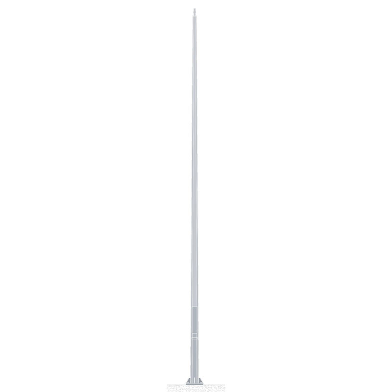
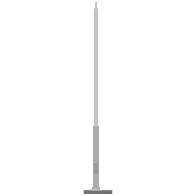
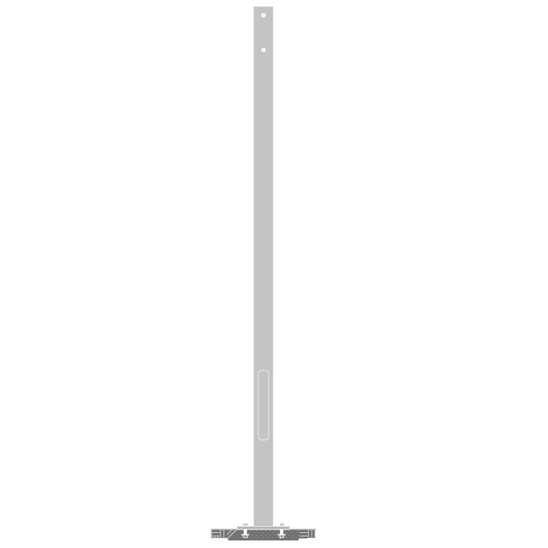
A steel light pole is a structural vertical column manufactured from steel — typically carbon steel, weathering steel, or galvanized steel — designed to support luminaires, traffic signals, signage, or other outdoor electrical equipment at a defined height above ground. Steel light poles are the most widely used pole type in municipal street lighting, highway illumination, sports facilities, commercial parking areas, and public infrastructure worldwide, valued for their combination of high load-bearing strength, long service life, dimensional versatility, and cost efficiency relative to aluminum or composite alternatives.
Unlike concrete or wooden poles, steel light poles can be precision-engineered to specific height, wall thickness, base diameter, and taper ratio requirements — and finished with a range of surface treatments to match architectural specifications or withstand harsh environmental exposure. They are available in straight, tapered, and decorative forms, from utilitarian galvanized highway poles to ornate multi-arm decorative columns for urban plazas and heritage streetscapes.
A well-specified Steel Light Pole serves as the structural backbone of an outdoor lighting system for 25 to 50 years — making material selection, surface protection, and engineering specification decisions at the procurement stage among the most consequential in any street lighting or area lighting project.
Content
- 1 How Steel Light Poles Are Manufactured
- 2 Types of Steel Light Poles by Design and Application
- 3 Steel vs. Aluminum vs. Concrete: Why Steel Is Often the Preferred Choice
- 4 Surface Treatment Options for Steel Light Poles
- 5 Structural Engineering and Load Design of Steel Light Poles
- 6 Key Specifications to Define When Sourcing a Steel Light Pole
- 7 Installation of Steel Light Poles: Key Steps and Common Errors
- 8 Maintenance and Service Life of Steel Light Poles
- 9 Steel Light Poles for European and Middle Eastern Markets
How Steel Light Poles Are Manufactured
The manufacturing process for steel light poles follows a defined sequence of forming, welding, finishing, and quality inspection operations. Understanding this process helps specifiers evaluate the quality and structural integrity of poles from different suppliers.
Steel Plate Selection and Cutting
Production begins with structural steel plate or hot-rolled coil, cut to precise dimensions based on the pole's height, diameter profile, and wall thickness specification. Common steel grades used include S235, S355 (EN 10025) and equivalent ASTM A572 or A36 grades. Higher-grade steels (S355 and above) are specified for taller poles, poles in high-wind zones, or poles carrying heavy luminaire arm assemblies. Steel plate thickness in light pole manufacturing typically ranges from 3 mm to 8 mm, with heavier walls used at the base section of taller poles where bending moments are highest.
Roll Forming and Tapering
Cut steel plate is cold-rolled into a conical (tapered) or cylindrical tube profile using CNC press brakes or roll-forming machines. Tapered poles — which are narrower at the top than at the base — are the most structurally efficient form, concentrating material where bending stress is greatest and reducing weight at the top where it contributes least to structural performance. A standard 10-meter tapered steel pole may have a base outside diameter of 168 mm and a top outside diameter of 76 mm, with the taper providing both aesthetic appeal and structural efficiency.
Longitudinal Seam Welding
The rolled tube is welded along its longitudinal seam using submerged arc welding (SAW) or MIG/MAG welding processes. The seam weld is a structural element of the pole and must be executed to the full penetration and quality standards required by the applicable structural welding code — typically AWS D1.1 or EN ISO 5817 Grade B. Seam weld quality is verified by visual inspection, dimensional checks, and where specified, non-destructive testing (magnetic particle or ultrasonic) to confirm freedom from internal defects.
Base Plate and Anchor Bolt Assembly
A steel base plate — sized and drilled to match the anchor bolt pattern of the foundation — is welded to the base of the pole shaft. The base plate weld is the most critically loaded connection in the entire pole structure, transferring bending moments and shear forces from the pole shaft into the foundation anchor bolts. Base plate welds are inspected using magnetic particle testing (MPI) on every production pole in quality-managed manufacturing facilities, and base plate design is governed by AASHTO LTS-6 or EN 40 standard requirements.
Surface Treatment and Finishing
After fabrication and pre-treatment (shot blasting to Sa 2.5 per ISO 8501-1), steel light poles receive one or more surface protection systems depending on the environmental exposure category and the client's aesthetic requirements. The principal finishing options are hot-dip galvanizing, powder coating, paint, or a combination of galvanizing plus powder coating (duplex system). Each finishing option is described in detail in the surface treatment section below.
Types of Steel Light Poles by Design and Application
Steel light poles are manufactured in a range of structural forms and decorative styles to suit different lighting functions and visual environments. The main categories are outlined below.
Round Tapered Steel Poles
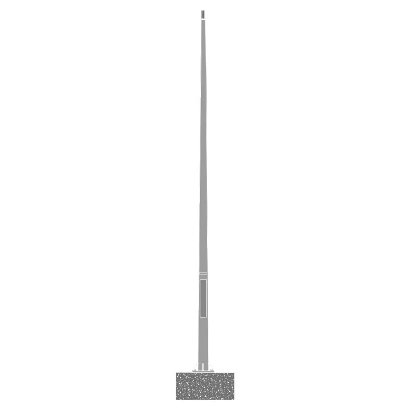
The most common form in municipal and highway lighting. A continuously tapered circular tube, typically 6 to 15 meters in height, supporting one or two luminaire arms at the top. The tapered profile is structurally efficient, reduces wind loading compared to a uniform cylinder of the same height, and is compatible with a wide range of single-arm and twin-arm bracket configurations. This is the standard pole form used in street lighting across Europe, the Middle East, and Asia-Pacific markets.
Decorative Steel Poles
Decorative steel light poles incorporate ornamental details — fluted shafts, scrolled brackets, cast iron-style base decorations, lantern-style luminaire housings, and multi-arm candelabra configurations — into their design while maintaining full structural performance. They are specified for heritage streetscapes, urban plazas, promenades, and commercial developments where the pole itself is an architectural element and not simply a functional structure. The Steel Light Pole designs developed for European and Middle Eastern markets frequently combine decorative profiles with hot-dip galvanized and powder-coated duplex finishes to achieve both visual quality and long service life in demanding climatic conditions.
High-Mast Steel Poles
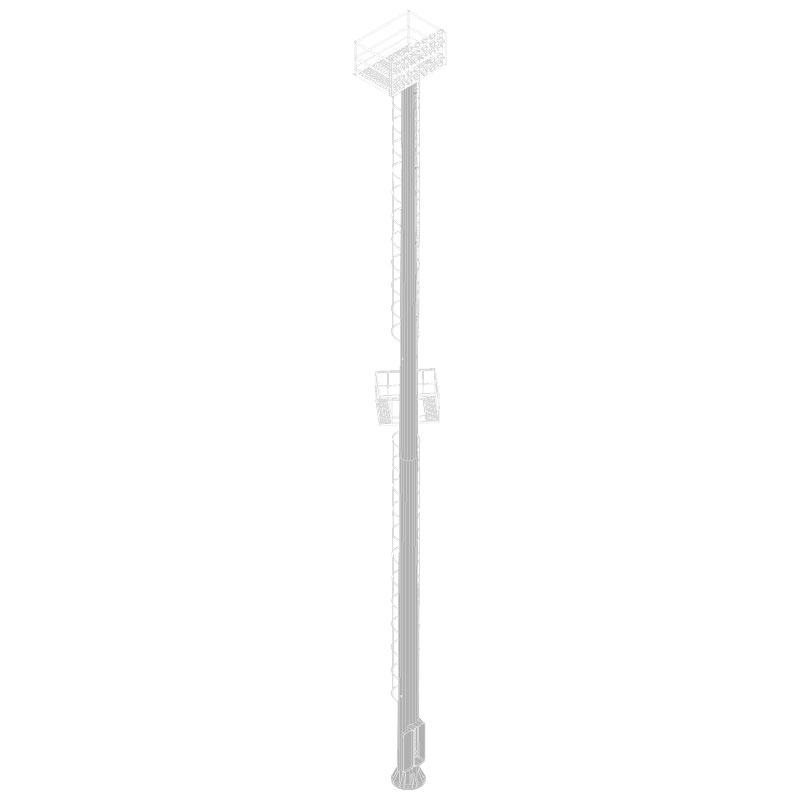
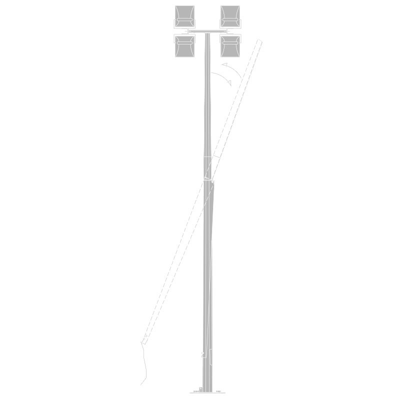
High-mast poles are tall steel structures — typically 20 to 45 meters in height — used to illuminate large open areas such as motorway interchanges, stadium parking areas, container ports, and airport aprons from a single central structure with a ring of luminaires at the top. High-mast poles are engineered as individual structural designs, with wall thickness, foundation, and anchor bolt design all calculated for the specific site wind speed, luminaire loading, and height. They frequently include a lowering device to allow the luminaire ring to be brought to ground level for maintenance without the need for mobile elevated work platforms.
Davit Arm and Side-Entry Poles
Davit arm poles incorporate a curved outreach arm as an integral part of the pole structure, positioning the luminaire over the carriageway or pathway without a separate luminaire bracket. Side-entry poles accept a horizontal arm inserted through a hole in the pole shaft, secured by a lock nut inside the pole. Both configurations are used in highway and urban street lighting, with the choice between them determined by the luminaire mounting height, outreach distance, and the aesthetic preference of the specifying authority.
| Pole Type | Typical Height | Primary Application | Key Structural Feature |
|---|---|---|---|
| Round Tapered | 6 to 15 m | Street lighting, highways | Continuous taper; single seam weld |
| Decorative / Ornamental | 4 to 10 m | Urban plazas, promenades, heritage areas | Multi-section; ornamental shaft and brackets |
| High-Mast | 20 to 45 m | Motorways, ports, stadiums, airports | Multi-section; flange-jointed; lowering device |
| Davit Arm | 6 to 12 m | Carriageway lighting, pathway lighting | Integral curved outreach arm |
| Side-Entry | 5 to 12 m | Street lighting, parking areas | Horizontal arm through shaft |
Steel vs. Aluminum vs. Concrete: Why Steel Is Often the Preferred Choice
The choice of pole material is a significant decision in any lighting project, affecting structural performance, service life, maintenance requirements, and total lifecycle cost. Steel remains the dominant material for outdoor light poles globally, and the reasons for this are well supported by engineering and economic evidence.
Structural Strength and Height Capability
Steel has a yield strength of 235 to 355 MPa for common structural grades, compared to 160 to 270 MPa for aluminum alloys used in pole manufacture. This higher strength-to-section ratio allows steel poles to achieve greater heights with thinner walls than equivalent aluminum poles — important for high-mast applications and for poles carrying heavy multi-arm luminaire configurations. For poles above 12 meters or in high-wind-speed zones (design wind speeds above 40 m/s per EN 1991-1-4), steel is almost universally the structural material of choice.
Impact Resistance and Fatigue Performance
Steel has a well-defined fatigue limit — below a certain cyclic stress amplitude, steel does not accumulate fatigue damage regardless of the number of loading cycles. Aluminum does not have a true fatigue limit; it continues to accumulate damage at any stress amplitude, which is a consideration in poles subject to high-frequency wind-induced vibration. For poles in exposed coastal or open-terrain environments where wind-induced vibration is a significant design loading, steel's fatigue behavior gives it a structural durability advantage over aluminum over a multi-decade service life.
Cost Efficiency at Scale
For large-scale municipal or highway lighting projects requiring hundreds or thousands of identical poles, hot-rolled steel is typically 30 to 50% lower in raw material cost per kilogram than structural aluminum alloy (based on London Metal Exchange historical pricing comparisons), and steel pole manufacturing is highly scalable with standard roll-forming and welding equipment. Concrete poles are economical for simple, low-height applications but lack the dimensional flexibility and aesthetic capability of steel for decorative or architectural applications.
Repairability and End-of-Life Value
Steel poles damaged by vehicle impact can in some cases be straightened and re-galvanized, extending their service life. At end of life, steel poles have significant scrap metal value — steel is the world's most recycled material, with a global recycling rate above 85% according to the World Steel Association (worldsteel.org, 2023). This end-of-life value partially offsets the initial capital cost of steel pole installations.
Surface Treatment Options for Steel Light Poles
Surface treatment is arguably the most important long-term performance variable for a steel light pole. The steel substrate has excellent structural properties but is susceptible to corrosion if the protective system is inadequate for the exposure environment. The right surface treatment extends pole service life to 40 to 50 years; the wrong one can result in visible corrosion and structural deterioration within 10 years.
Hot-Dip Galvanizing (HDG)
Hot-dip galvanizing involves immersing the fabricated steel pole in a bath of molten zinc at approximately 450°C, producing a metallurgically bonded zinc coating of typically 85 to 100 microns average thickness (per EN ISO 1461). Zinc provides sacrificial cathodic protection — it corrodes preferentially to the steel, protecting the base metal even at cut edges, drilled holes, and minor coating damage. HDG poles in moderate urban environments routinely achieve 25 to 40 years of maintenance-free service before first maintenance is required (Source: American Galvanizers Association, galvanizeit.org).
Powder Coating
Powder coating applies a thermosetting polymer coating — polyester, epoxy-polyester, or TGIC polyester — electrostatically to the steel surface and cures it at 180 to 200°C. Powder coating provides color uniformity, UV resistance, and a smooth or textured aesthetic finish in virtually any RAL or custom color. Coating thickness is typically 60 to 80 microns for standard polyester systems and 80 to 120 microns for heavy-duty or thermally resilient specifications. Powder coating alone does not provide cathodic protection and relies on coating integrity for corrosion resistance — making surface preparation (Sa 2.5 blast and zinc phosphate pretreatment) critical to adhesion and long-term performance.
Duplex System: Galvanizing Plus Powder Coating
The duplex system — hot-dip galvanizing followed by powder coating — combines the cathodic protection of zinc with the barrier protection and color capability of powder coating. This system delivers service life 1.5 to 2.5 times longer than either system used alone (Source: EN ISO 12944-5), making it the recommended finish for poles in coastal, industrial, or high-humidity environments where maximum corrosion resistance is required. The duplex system is the standard specification for decorative steel poles in Middle Eastern markets (high salt and humidity exposure) and coastal European installations.
Weathering Steel (Corten)
Weathering steel grades (such as S355J2W per EN 10025-5) form a stable, tightly adherent rust patina in outdoor exposure that acts as a barrier coating, slowing further corrosion without requiring galvanizing or paint. Weathering steel poles are specified for architectural and heritage lighting projects where the warm amber-brown patina finish is aesthetically desirable. They are not suitable for coastal or de-icing salt environments where chloride contamination prevents the formation of a stable patina and leads to progressive corrosion.
| Finish System | Typical Coating Thickness | Expected Service Life | Best Environment |
|---|---|---|---|
| Hot-Dip Galvanizing | 85 to 100 microns | 25 to 40 years | Urban, suburban, rural |
| Powder Coating only | 60 to 120 microns | 10 to 20 years | Low-corrosivity inland sites |
| Duplex (HDG + Powder) | 145 to 220 microns | 40 to 60+ years | Coastal, industrial, Middle East |
| Weathering Steel | Self-forming patina | 30 to 50 years (suitable sites) | Inland, low-chloride environments |
Structural Engineering and Load Design of Steel Light Poles
A steel light pole is a structural element subject to defined design loads, and its dimensions — height, base diameter, top diameter, and wall thickness — must be engineered to satisfy those loads with the required safety factors. Specifying a pole on the basis of height alone, without structural engineering for site-specific wind and equipment loads, is a common error that can result in pole failure under extreme weather events.
Wind Loading: The Critical Design Load
Wind is the dominant structural load on a light pole in virtually all locations. The design wind pressure on a pole shaft and luminaire assembly is calculated from the site reference wind speed using the appropriate wind loading standard — EN 1991-1-4 (Eurocode 1) in Europe, AASHTO LTS-6 in North America, and equivalent national standards elsewhere. Design wind speeds for structural lighting calculations typically range from 28 m/s in sheltered urban areas to 50 m/s or more in exposed coastal or typhoon-prone regions.
The bending moment at the base of the pole — the critical structural check — is the product of the total wind force on the pole shaft and luminaires multiplied by their respective heights above ground. For a 10-meter pole with a 10 kg luminaire and single outreach arm in a 40 m/s design wind speed zone, the base bending moment may be on the order of 15 to 25 kNm, which determines the minimum required pole wall thickness and base diameter for the specified steel grade.
Foundation and Anchor Bolt Design
The pole foundation must transfer the base bending moment and shear force from the anchor bolts into the surrounding soil or rock. Foundation design depends on the soil bearing capacity (from site investigation data), the design base moment, and the applicable foundation design standard (EN 1997 Eurocode 7 or equivalent). Anchor bolts for steel light poles are typically M24 to M36 high-tensile bolts in groups of 4 or 6, set in a concrete foundation cast to the specified bolt pattern and projection dimensions.
Vibration and Dynamic Loading
Slender steel poles in exposed locations can be susceptible to wind-induced vortex shedding — a phenomenon where alternating vortices shed from opposite sides of the pole shaft induce oscillations at the pole's natural frequency. If the vortex shedding frequency matches the pole's natural frequency, resonant oscillation can develop, leading to fatigue damage at the base weld over time. Helical strake attachments, tuned mass dampers, or modified shaft geometry are engineering solutions used to detune the pole's response to vortex shedding in susceptible applications.
Key Specifications to Define When Sourcing a Steel Light Pole
Procuring steel light poles without a complete technical specification is a common source of quality disputes and performance failures. The following parameters should be defined in any pole procurement specification.
- Mounting height: The height of the luminaire mounting point above finished ground level, in meters. This is not the same as the overall pole length, which includes the below-ground embedded section or the anchor bolt flange projection.
- Steel grade: Specify the EN or ASTM grade — e.g., S355J2 per EN 10025-2. Higher-grade steel (S355 vs S235) allows lighter, thinner walls for equivalent structural performance.
- Wall thickness: Minimum wall thickness at the base and top of the pole shaft, in millimeters. For most street lighting poles, base wall thickness ranges from 4 mm to 6 mm; thicker walls are needed for high poles or heavy luminaire loads.
- Base and top outside diameter: The outer diameter at the base and tip of the pole, in millimeters. These dimensions determine the visual proportions, the taper ratio, and the structural section modulus available at each height.
- Design wind speed: The site reference wind speed used for structural design, in m/s, referenced to the applicable wind loading standard. This must match the site location and exposure category.
- Luminaire and arm loading: The total weight and projected area of the luminaire(s) and arm assembly(ies) to be mounted on the pole. These are essential inputs for structural design.
- Surface finish system: Specify the complete finish system — blast standard, primer, galvanizing specification (EN ISO 1461 minimum zinc coating weight), powder coat color (RAL number), and coating thickness.
- Cable entry and internal wiring provisions: Specify whether a cable entry hole is required, its location and diameter, the handhole opening dimensions and cover type, and any internal cable management features.
- Applicable standards: State the structural design standard (EN 40 series for Europe; AASHTO LTS-6 for North America) and the welding inspection standard to which the pole must be manufactured and certified.
Installation of Steel Light Poles: Key Steps and Common Errors
Correct installation is as important as correct specification. A well-engineered and well-manufactured pole can fail prematurely if installed incorrectly — particularly if the foundation is undersized, the anchor bolts are misaligned, or the base plate connection is not properly executed.
- Foundation preparation: Excavate to the specified depth and pour the concrete foundation with the anchor bolt template positioned precisely at the correct location, level, and orientation. Anchor bolt projection above the top of the concrete must match the pole base plate hole pattern and nut engagement length specified in the pole design drawings.
- Concrete cure: Allow the foundation concrete to reach its specified 28-day compressive strength before installing the pole. Attempting to erect poles on freshly poured or partially cured foundations risks bolt pull-out or foundation cracking under the pole's self-weight and wind load during construction.
- Pole erection: Lift the pole using a crane or suitable lifting vehicle with a spreader bar or certified lifting attachment. Never lift a steel pole by the luminaire arm or by wrapping a chain directly around the shaft without padding — both methods risk deforming the shaft or damaging the surface finish.
- Plumbing and leveling: After setting the pole on the anchor bolts, check vertical alignment (plumb) in two perpendicular directions using a spirit level or optical level. Level is typically achieved by adjusting the leveling nuts below the base plate. Maximum permitted out-of-plumb for street lighting poles is typically 1 in 500 (0.2%) of the mounting height per EN 40-5.
- Bolt torquing: Tighten the anchor bolt nuts in a cross-pattern sequence to the specified torque value — typically calculated from the bolt diameter and grade using the formulae in the structural design documentation. Over-torquing can yield high-tensile anchor bolts; under-torquing leaves the base plate connection loose, allowing movement that causes fatigue cracking of the base weld over time.
- Base plate grout filling: Where specified, fill the void between the base plate and the concrete surface with a non-shrink cementitious grout to provide full bearing and exclude water from the anchor bolt zone. This is particularly important in aggressive corrosion environments where water ponding in the base plate void would accelerate corrosion of the anchor bolts.
Maintenance and Service Life of Steel Light Poles
With correct specification, surface treatment, and installation, steel light poles require minimal maintenance over most of their service life. However, a planned inspection and maintenance program extends service life, identifies problems before they become failures, and supports the asset management obligations of public lighting authorities.
Recommended Inspection Intervals
Most public lighting authorities implement a periodic structural inspection program for steel light poles. The UK Highways Agency (now National Highways) guidance and the Street Lighting Operational Group (SLOG) in the UK recommend visual inspection every 6 years and detailed structural inspection every 12 years for standard street lighting columns (Source: Highways England, Design Manual for Roads and Bridges, CS 160). For poles in aggressive environments (coastal, industrial, or high-traffic impact risk), shorter inspection intervals of 3 to 6 years are more appropriate.
What to Inspect
- Base corrosion: The zone from 150 mm below to 150 mm above ground level is the highest corrosion risk area — trapped moisture, de-icing salt, and soil contact combine to accelerate corrosion at the base of the shaft. Internal corrosion from water ingress through the handhole or cable entry is also common in this zone.
- Vehicle impact damage: Visual inspection for dents, bends, or deformations in the lower shaft. Even apparently minor dents reduce the structural capacity of the pole section and should be assessed by a structural engineer before the pole is returned to unrestricted service.
- Coating condition: Check for areas of coating breakdown, rust staining, chalking of powder coat, or delamination that indicate active corrosion below the surface coating and require maintenance intervention.
- Base plate and anchor bolts: Check for corrosion of the base plate, anchor bolt threads, and nut faces. Corroded anchor bolts may have reduced tensile capacity even if visually intact, and should be ultrasonically tested or replaced if significant corrosion is present.
- Handhole cover and door: Confirm the handhole cover closes and seals correctly, preventing water ingress into the pole interior. A loose or missing handhole cover admits water that pools at the base and accelerates internal corrosion — one of the most common causes of premature pole failure.
Refurbishment and Coating Renewal
When galvanizing or powder coating shows significant breakdown, the pole can be refurbished in situ or removed and returned to the manufacturer for re-blasting and re-coating. In-situ refurbishment using zinc-rich epoxy primer and polyurethane topcoat can restore corrosion protection to galvanizing-equivalent performance for a further 15 to 20 years at significantly lower cost than pole replacement — provided the steel section thickness is within the minimum structural requirement confirmed by ultrasonic thickness testing.
Steel Light Poles for European and Middle Eastern Markets
European and Middle Eastern street lighting specifications share a common requirement for high-quality, architecturally considered pole designs combined with maximum corrosion resistance — but the environmental and regulatory contexts differ significantly between the two markets.
In European markets, street lighting poles are governed by the EN 40 series of standards, which cover structural design, material specifications, dimensional tolerances, testing methods, and installation requirements. Urban European authorities increasingly specify decorative steel poles with duplex finish systems for principal streets, plazas, and transportation hubs, where the pole's visual quality contributes to the streetscape character and the finish must withstand decades of exposure without maintenance.
In Middle Eastern markets — particularly in the Gulf Cooperation Council (GCC) countries — the combination of high ambient temperatures (regularly exceeding 45°C), intense UV radiation, sand abrasion, and coastal salt-laden air in many coastal cities creates one of the most demanding corrosion environments for steel structures globally. Poles specified for these markets require duplex finish systems as standard, with powder coating formulated for high UV resistance and minimum gloss retention of 50% after 2,000 hours of UV exposure per EN ISO 11507. Salt spray resistance of 1,000 hours minimum per EN ISO 9227 is a common specification requirement for poles in GCC coastal locations.
The Steel Light Pole designs developed specifically for European and Middle Eastern applications combine structural engineering to local wind loading standards with duplex surface protection and decorative profiles suited to the architectural languages of both markets — providing a pole solution that meets both performance and aesthetic requirements without compromise.